Comprehensive Guidance for Reliable and Efficient IT Infrastructure Spaces
Server and Intermediate Distribution Frame (IDF) room design must satisfy rigorous technical requirements to ensure optimal performance, reliability, and maintainability. A robust design addresses critical aspects such as power provisioning, cooling strategies, rack layout, structured cabling, grounding, uninterruptible power supplies (UPS), and cable labelling. This article delves into the core technical considerations for each area, providing best practices for modern data and network environments.
Power Requirements and Distribution
Reliable power delivery is fundamental to server and IDF room operation. The design must begin with a load calculation that considers the total anticipated equipment draw, factoring in future scalability. Utilise redundant power feeds wherever possible, each protected by dedicated circuit breakers. Power Distribution Units (PDUs) should be installed in each rack, with monitoring capabilities for current, voltage, and environmental metrics.
All critical infrastructure must be connected to a UPS system sized for both the expected load and anticipated expansion. Select double-conversion (online) UPS systems for sensitive electronics to provide continuous, clean power. Power circuits should be colour-coded and clearly labelled for distinction between redundant A and B feeds. All electrical components must comply with local codes and standards, such as NEC or IEC, and provide proper overcurrent protection. Implement emergency power-off (EPO) switches in accessible but secure locations.
Cooling and Airflow Management
Thermal management is paramount to system longevity and reliability. Implement a precision cooling system designed for the specific room load, with capacity for peak conditions and N+1 redundancy. Employ hot aisle/cold aisle containment strategies to manage airflow efficiently. Racks should be arranged so that the fronts face each other (cold aisle) and backs face each other (hot aisle). Perforated floor tiles should be placed in the cold aisle to deliver conditioned air directly to equipment in raised floor environments.
Blanking panels must be installed in empty rack spaces to prevent recirculation of hot air. If using overhead return plenums, ensure there are no obstructions above racks. Utilise Computational Fluid Dynamics (CFD) modelling during design to predict airflow patterns and eliminate hotspots. Temperature and humidity sensors should be deployed at various points within the room to monitor environmental conditions in real time, with alerts for deviations outside of ASHRAE recommended ranges.
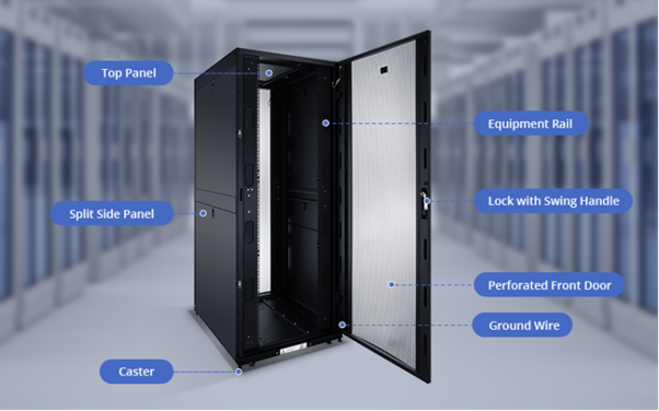
Rack Layout and Placement
Rack selection and positioning influence both equipment density and serviceability. Racks must be of standard width (typically 19 inches) with adequate depth and height for current and expected equipment. Allow a minimum of 1.2 metres (4 feet) of clearance in front of and behind each rack for service access. Position racks perpendicular to air distribution paths to support hot aisle/cold aisle containment. Secure racks to the floor or overhead bracing to mitigate seismic risk or accidental movement.
Plan for expansion by leaving designated empty rack spaces. Provide space for network switches, patch panels, and cable managers within the racks. Avoid placing racks directly under air conditioning supply outlets or return grilles to prevent condensation or airflow disruption.
Structured Cabling Routing and Cable Management
Structured cabling must be designed for flexibility, scalability, and minimal signal degradation. Use Category 6A or higher rated cabling for copper Ethernet runs and OM4 or higher for multimode fibre. Segregate horizontal and vertical cable pathways using cable trays, ladder racks, or basket trays. Route power and data cabling in separate trays to prevent electromagnetic interference (EMI).
Cables should enter racks from the top or bottom as dictated by the floor plan. Use horizontal and vertical cable managers within racks to maintain bend radius and orderly arrangement. Employ Velcro straps instead of zip ties for cable bundling to avoid excessive compression and potential damage. Maintain proper slack management to accommodate future changes without excessive coiling.
Grounding and Bonding
Proper grounding and bonding are vital for personnel safety and equipment protection. Install a dedicated telecommunications grounding busbar (TGB) within the server or IDF room as part of the building’s grounding system. All racks, cable trays, and metallic enclosures must be bonded to the TGB using conductors sized per local codes. Use exothermic welds or compression lugs for connections to ensure durability and low resistance.
Ground all shielded cabling, equipment chassis, and racks according to TIA/EIA-607 standards. Regularly inspect bonds and connections for corrosion or mechanical damage. Provide antistatic flooring where sensitive electronics are handled.
UPS Integration
Uninterruptible power supplies are critical for ensuring continuous operation during power disturbances. Select a UPS system with sufficient runtime to allow for orderly shutdown or failover to generator backup. Integrate UPS systems with network management cards to enable remote monitoring, event logging, and alerting. UPS maintenance bypass panels should be installed to permit servicing without interruption of protected loads. Battery monitoring and scheduled testing are essential to verify readiness.
For high-availability environments, deploy redundant UPS systems in parallel, with load-sharing capabilities. Ensure that both utility and UPS power inputs are clearly labelled and regularly tested.
Cable Labelling Standards
Consistent cable labelling streamlines troubleshooting and future modifications. Adopt industry standards such as TIA-606-C for labelling schemes. Labels must be machine-printed, durable, and affixed to both ends of every cable. Information should include origin, destination, cable type, and unique identifier. Labels on fibre cables should also indicate polarity and strand count.
Maintain a comprehensive documentation system, mapping all cable routes, pathways, and terminations. Update records promptly when changes occur to preserve the integrity of the infrastructure. Provide schematic diagrams and labelling legends within the room for quick reference.
Conclusion
Optimal server and IDF room design is an interdisciplinary effort requiring careful attention to power, cooling, rack layout, structured cabling, grounding, UPS integration, and cable labelling. Implementing best practices in each area minimises downtime, facilitates maintenance, and extends the lifespan of critical IT assets. Continual adherence to technical standards and proactive monitoring are essential for meeting the demands of modern digital enterprises. Consult your ATODE IT expert for advice on server room and IDF design.